ECE 581: High Frequency Power Electronics

Raspberry Pi Pico Modulator Example Code
Details of Pi Pico
- Pi Pico Pinout
- RP2040 Datasheet
- Pi Pico MicroPython Getting Started Guide
Example MicroPython Modulator Code
- Starter Code to generate 7 PWM signal pairs
Programming the Pi Pico
- RP2040mem.py
- RP2040_PWM.py
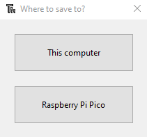
- RP2040_GPIO.py From within Thonny, with the pi pico connected, open each of the three files and select "save copy". As long as the pi pico is connected and recognized, you will receive the following window:
To get started programming the Pi Pico, follow the Pi Pico MicroPython Getting Started Guide from the begging until the "Use the Shell" step. At this point, you can upload the ECE 581 Starter Code to the pi pico and modify this code to generate the PWMs required for your design.
Note that you need to upload the three library files onto the pi pico.
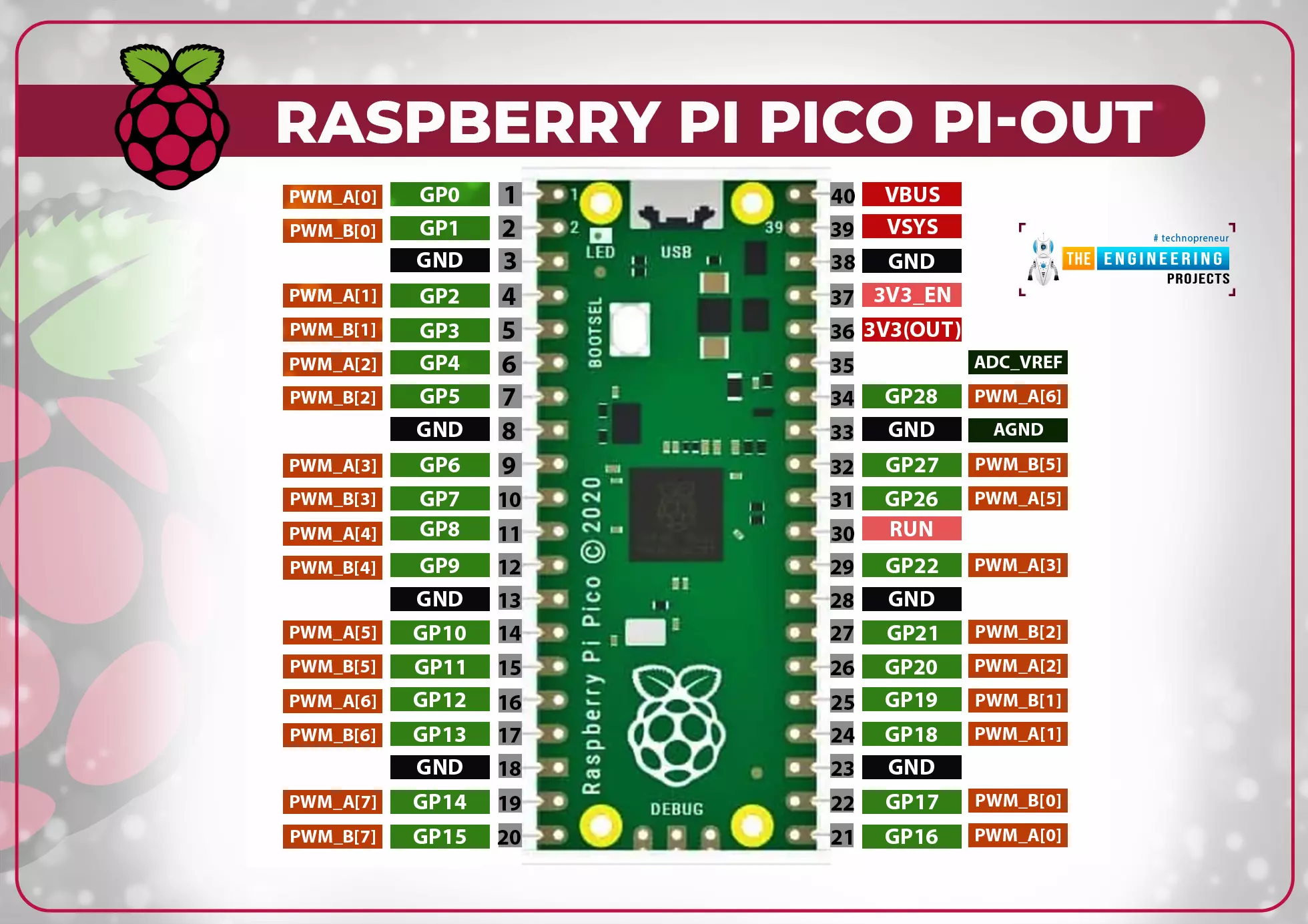
Without modificaiton, the example code will generate three PWM signal pairs for PWM channels 0, 1, and 2. These six signals can be observed on GPIO0-GPIO6 (pins 1-2, 4-7, & 9). All will output 150 kHZ PWM signals, with 40ns deadtimes and varying phase shift and duty cycle.
Example of Pico code modification
- channel is an integer in the range 0-7 which will choose which PWM module to configure. For example, channel=2 configured PWM2A and PWM2B as two complementary signals. They will later be output on GPIO4 and GPIO5 (pins 6 and 7), per the pinout diagram
- period is an integer less than 216 that defines the switching period in clocks of the system clock (set to 250 MHz in this code by default).
- duty is a number between 0 and 1 that defines the high duty cycle of the A signal in each PWM channel. Because the signals are complementary, the B signal will have complementary duty cycle. For example, ignoring deadtime, if duty=0.25, then PWMA will have 25% duty cycle and PWMB will have 75% duty cycle.
- deadtime, like period, is defined in number of clocks of the system clock. For a 250 MHz system clock, deadtime=10 gives 40 ns deadtimes. The deadtimes are subtracted equally from the rising and falling edges of the PWM signal and as such will slightly decrease the positive duty cycle of each signal.
- phase is also defined in number of clocks, and advances the signal by the corresponding amount. This can be used to generate a maximum of one half-period of phase shift, i.e., phase <= period/2 is required. If you need larger phase shifts between signals, you can swap the A and B outputs from the PWM channel to get and additional period/2 shift.
The example code consists of the library files which you loaded onto the Pi Pico in the previous section, and the main file PiPicoModulatorExample.py. The following explains the code segments in this main file. Though this code relies on the library files, the details of the libraries won't be reviewed.
The first section of code sets the Pi Pico clock frequency to 250 MHz.
#from machine import Pin, PWM, freq, mem32, mem16, mem8, lightsleep, idle, enable_irq
from machine import freq, idle
import RP2040mem as MEM


#Set system clock to 250 MHz
sysClock = const(250_000_000)
freq(sysClock)

#Test to make sure frequency is stable
print(freq())
The default maximum clock frequency for the Pi Pico is 125 MHz. However, considering the limited amount of hardware we will be using, this can be exceeded without issue. This code sets the clock to 250 MHz, then prints the current system clock frequency to the shell. This print statement makes sure that the new clock frequency is stable. If, for any reason, the code hangs without this print statement completing, 250 MHz may be too high for your hardware, and you can reduce this number until stable operation is achieved. Alternately, you can also increas from the default 125 MHz. A higher system clock allows greater resultion of the modulated signals.
The next block sets all PWM outputs (GPIO 1-15) low. This ensures that there is no output while configuring the PWMs. Next, the code defines the intended switching frequency (in Hz) and uses it to find the switching period in number of system clocks. For a 250 MHz system clock and 150 kHz switching frequency, Tperiod=1,666.
# Set GPIO 1-15 low during configuration
MEM.GPIO.setAllPWMsLow()

#Set switching frequency to 150 kHz
switchFreq = 150_000
Tperiod = int(sysClock/switchFreq)
The next section defines all the PWM signals that the pi pico will output. The setPWMpair() function configures a pair of complementary PWM signals corresponding to one of the Pi Pico PWM channels. See, for example, this pinout diagram for pin assignments. Some PWMs can be routed to multiple pins, but this code only uses the GPIO1-15 (pins 1-20) as PWM outputs.
#Setup PWM pairs
#	period, deadtime, and phase are in # of clocks
#	duty is a value between 0 and 1
#	phase cannot go beyond one half period.  For higher phase shifts, swap use of A and B channels
MEM.PWM.setPWMpair(channel=0, period=Tperiod, duty=.5, deadtime=10, phase=0)
MEM.PWM.setPWMpair(channel=1, period=Tperiod, duty=.5, deadtime=10, phase=Tperiod/2)
MEM.PWM.setPWMpair(channel=2, period=Tperiod, duty=.25, deadtime=10, phase=100)
There are five input arguments to the setPWMpair() function.
The final block of code turns on all PWM channels, then sets GPIO 1-15 as PWM outputs.
# Turn on all PWMs
MEM.PWM.turnOnAllPWMs()

# Set GPIO 1-15 as PWM outputs
MEM.GPIO.setAllPWMsOUT()

print('done')
idle()
Finally, the code prints 'done' to the shell then allows the microcontroller to idle. This final shell print is useful for debugging to ensure the entirety of the PWM setup code was executed.