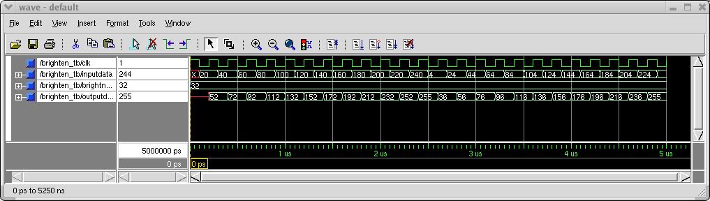
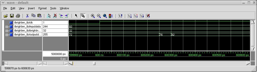
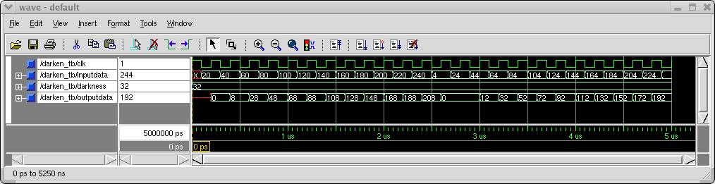
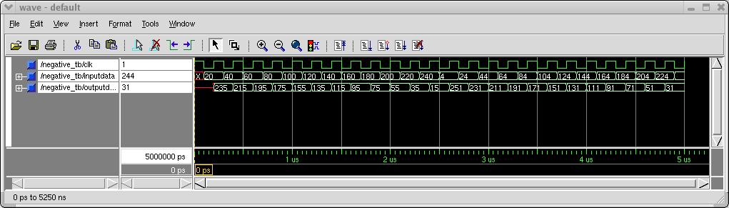
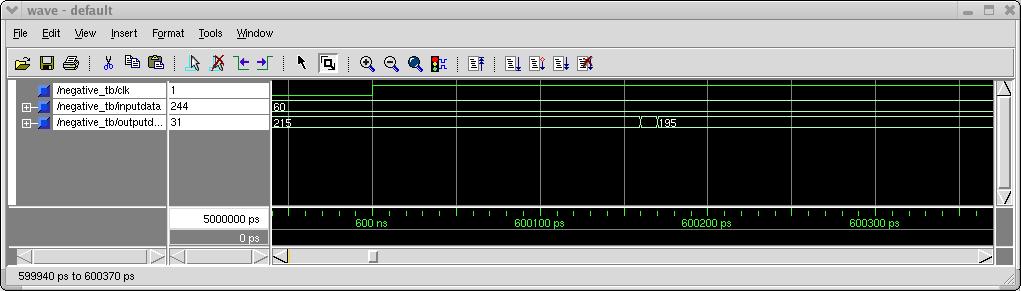
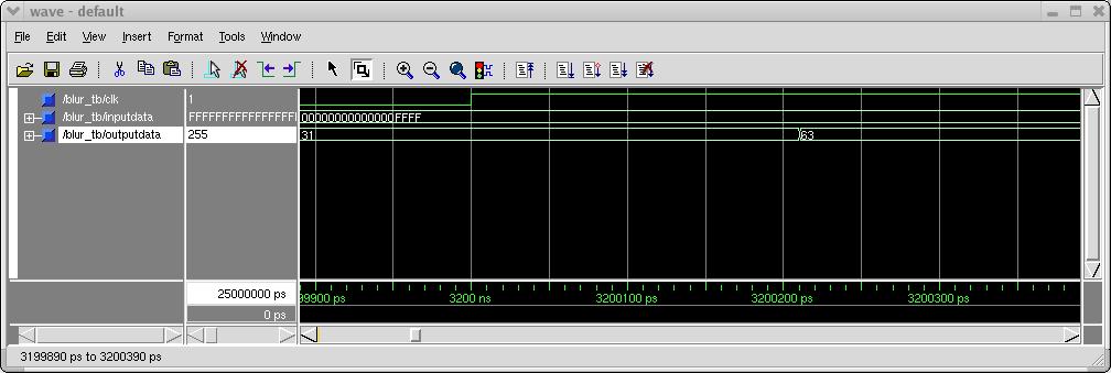
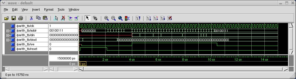
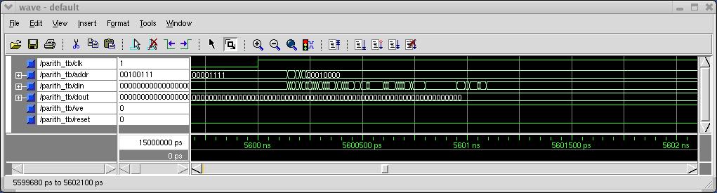
TSMC 0.18 ASIC ImplementationModule TestingSimilar to implementing the design on the Xilinx Virtex FPGA, retargeting the design for the TSMC 0.18 ASIC was a multi-step process. First, each individual module was tested using post-layout simulation. The results of the post-layout simulation for each module are given below along with the layouts. The "Wide" pictures look identical to the pre-layout simulation (as expected), but after zooming in on the simulation, a small delay is visible. Also given here are the verilog files generated by the synthesis step and the time_sim.sdf files generated by Silicon Ensemble to allow the reader to recreate these results.Wide Zoom Layout Verilog Netlist time_sim.sdf - Brighten Module Post-Layout Wide Zoom Layout Verilog Netlist time_sim.sdf - Darken Module Post-Layout Wide Zoom Layout Verilog Netlist time_sim.sdf - Negative Module Post-Layout Wide Zoom Layout Verilog Netlist time_sim.sdf - Blur Module Post-Layout Complete Design TestingInitiallly, our design was successfully implemented in the TSMC 0.18 ASIC, but post-layout simulations failed. This was because the Xilinx Virtex 1000E initializes all registers to logical zero on startup, a characteristic not shared by the custom ASIC. To fix this, we added a reset signal to the controller which initializes the state register in the finite state machine to zero. This required a minor change to the controller vhdl file and the controller testbench. These updated files are available on the Source Files page.After making these minor changes, the post-layout simulations for the complete design matched the pre-layout simulations and the small delay could be seen on the zoom picture. These results are given below. Wide Zoom Verilog Netlist time_sim.sdf - Controller Post-Layout TSMC 0.18 micron Layout [ Figure 9. TSMC 0.18u Layout (with ATPG) ] |