Power system model (Back to the homepage)
The library is built on the modified WECC 179-bus, 29-machine system (originally reported in Electric Power Research Institute, “DC multi-infeed study,” EPRI TR-104586s, Projects 2675-04-05, Final Report 1994). This system is representative for actual bulk power systems in terms of the topology, parameters and the structure of oscillations. See details about the base case.
The source of undamped natural oscillation is created by assigning negative value(s) of the damping parameter D to a specific generator or to a group of specific generators.
For modelling of forced oscillations, one of the generators is modelled with excitation system by using the model GENROU, whose parameters take a set of typical parameters and may not match the real Western Interconnection system. Note that all GENROU models used in different cases in this website share the same set of parameters except for the inertia parameter. Periodic disturbance is injected into a reference point of the excitation system and modelled in time domain by using a User Defined Model of the TSAT software.
Fig.1 illustrates the model of external force in the excitation system with sinusoidal-wave injection of 0.08p.u. magnitude and 0.86Hz.
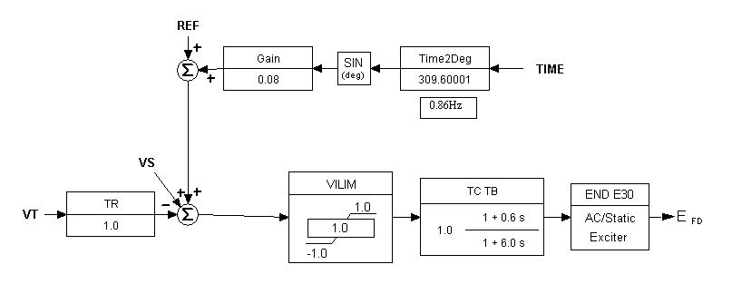
Figure 1. Block diagram of excitation system with injected sinusoidal-wave disturbance
Fig.2 illustrates the model of external force in the excitation system with rectangular-wave injection.
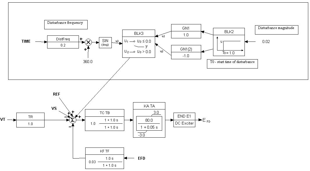
Figure 2. Block diagram of excitation system with injected rectangular-wave disturbance
The waveform of the injected periodic signal in the reference point is shown in Fig.3, whose spectrum contains only odd harmonics of the fundamental frequency 0.2Hz as shown in Fig4. It can be seen that the higher the frequency of harmonic is, the lower the magnitude.
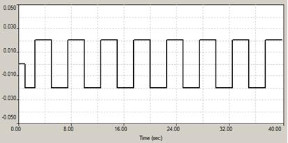
Figure 3. Waveform of the injected periodic disturbance
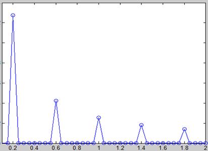
Figure 4. Spectrum of the injected periodic disturbance
For poorly damped natural oscillations, the transient is excited by a three-phase short circuit applied to the terminal bus of a specific generator. The fault is cleared after 0.01-0.05s and the post-fault system topology remains the same as pre-fault. Note that short circuit is not applied for the forced oscillations.