|
The
Synopsys Designware's Asynchronous Dual Port
RAM (DW_ram_r_w_a_dff_inst.vhd) was instantiated in our project for
the Input and the Output RAM respectively. This RAM has the following
features:
-
Parameterized
Word Depth – This was set to 16 for our project
-
Parameterized
Data Width – This was set to 32 bits for our project
-
Asynchronous
Static Memory
Description of the Input RAM and the Output RAM
Input
RAM
The Data Encryption Standard IP block requires the inputs: key
(64 bit) and the plain text (64 bit) to be encrypted respectively. The
function of the Input RAM is to store the input values in its contiguous
locations. The RAM IP has a data width of 32 bits. Therefore, the key and
plain text had to be stored as two words of 32 bits each in successive
locations. In our case, the key was stored in locations “0000” and
“0001” respectively and the plain text was stored in locations
“0010” and “0011” respectively. This is for the first set of input
data. For all the data, the same sequence is followed from location
“0100" onwards. The controller (state machine) was implemented for
two set of input data. (Please refer to the User Guide for the usage of
RAM signals). The following figure shows
the block diagram of the Input RAM and its signals.
Output
RAM
The Data Encryption Standard
IP block encrypts the plain text using
the key input and computes the ciphered text (64 bits). The function of
the Output RAM is to store the output values in its contiguous locations.
The Output RAM IP uses a data width of 32 bits. Therefore, the ciphered
text had to be stored as two words of 32 bits each in successive
locations. In our case the ciphered text corresponding to the first set of
input data would be stored in locations “0000” and “0001”
respectively.
|
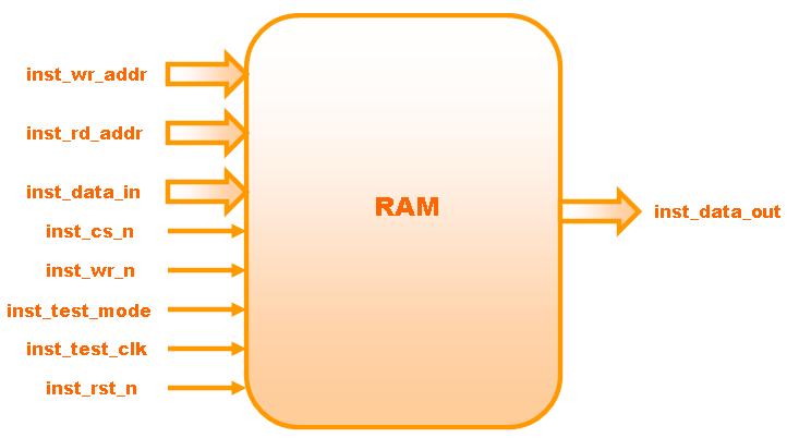
Figure:
Block Diagram of the RAM |
|