Default Address Allocation
HARDWARE AND SOFTWARE DETAILS
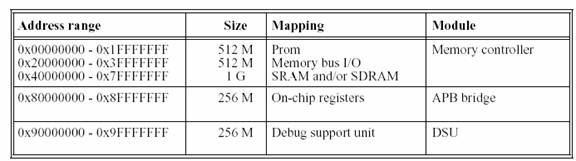
LEON uses the AMBA-2.0 AHB bus to connect the processor cache controllers to the memory controller and other (optional) high-speed units. In the default configuration, the processor is the only master on the bus, while two slaves are provided: the memory controller and the APB bridge. Table below shows the default address allocation.
Default Address Allocation
From the above address space it is evident that we can read and write to APB devices in the range 0x80000000 – 0x8FFFFFFF. The APB bridge is connected to the AHB as a slave and acts as the (only) master on the APB. Most on-chip peripherals are accessed through the APB.
The processor is connected to the AHB through the instruction and data cache controllers. Access conflicts between the two cache controllers are resolved locally and only one AHB master interface is connected to the AHB. The processor will perform burst transfers to fetch instruction cache lines or reading/writing data as results of double load/store instructions. Byte, half-word and word load/store instructions will perform single.
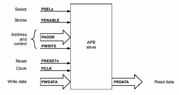
For a write
transfer the data can be latched at the following points:
on either
rising edge of PCLK, when PSEL is HIGH
on the rising
edge of PENABLE, when PSEL is HIGH.
The select signal PSELx, the address PADDR and the write
signal PWRITE can be combined to determine which register should be
updated by the write operation. For read
transfers the data can be driven on to the data bus when PWRITE is LOW
and both PSELx and PENABLE are HIGH. While PADDR is used to
determine which register should be read.
APB Device
The
APB device is connected using the following two records:
PSEL: Std_ULogic;
PENABLE: Std_ULogic;
PADDR:
Std_Logic_Vector(PAMAX-1 downto 0);
PWRITE: Std_ULogic;
PWDATA:
Std_Logic_Vector(PDMAX-1 downto 0);
end
record;
type
APB_Slv_Out_Type is record
PRDATA:
Std_Logic_Vector(PDMAX-1 downto 0);
end
record;
We interfaced a memory element to this bus and performed read and write to these registers from the external ram using a C-application code. The file apb_slave.vhd shows the description of the interfaced registers. The registers are interfaced to the address space 0x80000300 – 0x8000030C.
The
following is the entity of the added device.
entity apb_slave is
port (
rst : in
std_logic;
-- Reset Input for the module
clk : in
clk_type;
-- Clock Input for the module
apbo : out apb_slv_out_type
-- AMBA APB slave outputs
end apb_slave;
Since this is a new
device in the
ram.dat:leon_test.exe
sparc-rtems-objcopy
--remove-section=.comment leon_test.exe
sparc-rtems-objdump -s
leon_test.exe > ram.dat
sparc-rtems-objdump -d
leon_test.exe > ram.s
sparc-rtems-size leon_test.exe
sparc-rtems-objcopy -O srec lt
sdram.rec
leon_test.exe
: regtest.o irqctrl.o uart.o leon_test.o timers.o cache.o misc.o \
memtest.o ioport.o fpu.o
ramtest.o divtest.o multest.o
$(CC) $(LDFLAGS) regtest.o
irqctrl.o uart.o leon_test.o timers.o cache.o misc.o \
memtest.o ioport.o fpu.o
ramtest.o \
divtest.o
multest.o \
$(LIBS) -o leon_test.exe
cp leon_test.exe lt
sparc-rtems-strip leon_test.exe
The resultant RAM-LEON-RAM is passed through the modelsim
for simulation using the standard test bench and using the standard way to
conduct the test as described in
Once this is passed the synthesis of the same RAM-LEON-RAM is done using fc2_shell and dc_shell. synthesis results are here.
The snapshot of the Modelsim window showing successful simulations. The testbench involves forceful breakpoint introduction to stop the processor however the message "TEST COMPLETED,OK" shows completion of the test.
A snap-shot of post-synthesis simulation is shown below.
APB is a simple and fast enough bus for low-end peripherals mostly for ones which operate on word by word of the data rather than a burst of data. The control logic in this type of bus is simple and thus in the place of current memory can be easily replaced with any peripheral devices. The examples of such devices can be seen in Leon’s built in Timers(timers.vhd), I/Oport(ioport.vhd), irqCtrl(irqctrl.vhd) in which Jiri Gaisler already coded them as APB devices.
AHB
AHB is a new
generation of AMBA bus which is intended to address the requirements of
high-performance synthesizable designs. AMBA AHB is a new level of bus which
sits above the APB and implements the features required for high-performance,
high clock frequency systems including:
burst transfers
split transactions
single cycle bus
master handover
single clock edge
operation
non-tristate
implementation
wider data bus
configurations (64/128 bits).
incrementing
bursts, which do not wrap at address boundaries
wrapping
bursts, which wrap at particular address boundaries.
an address and
control cycle
one or more cycles
for the data.
The address cannot
be extended and therefore all slaves must sample the address during this time.
The data, however, can be extended using the HREADY signal. When LOW this
signal causes wait states to be inserted into the transfer and allows extra time
for the slave to provide or sample data. During a transfer the slave shows the
status using the response signals, HRESP[1:0]: OKAY, ERROR, RETRY.
In normal operation
a master is allowed to complete all the transfers in a particular burst before
the arbiter grants another master access to the bus. However, in order to avoid
excessive arbitration latencies it is possible for the arbiter to break up a
burst and in such cases the master must re-arbitrate for the bus in order to
complete the remaining transfers in the burst.
An AHB master has the most complex bus interface in an AMBA system. Typically an AMBA system designer would use pre-designed bus masters and therefore would not need to be concerned with the detail of the bus master interface[2]. The interface of the AMBA AHB is as shown in the following figure.
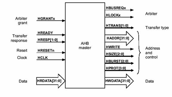
AHB Master Interface
The master device request for bus access by making the HBUSREQx signal high. The arbiter responds to the request and should set the HGRANTx in the input to high and HREADY high indicating the complete access to the bus, upon detecting both the input signals HGRANTx and HREADY high the device can start the transfer.
Each AHB master is connected to the bus through two records:
--
AHB master inputs (HCLK and HRESETn routed separately)
type
AHB_Mst_In_Type is record
HGRANT: Std_ULogic; --
bus grant
HREADY: Std_ULogic; --
transfer done
HRESP: Std_Logic_Vector(1
downto 0); -- response type
HRDATA:
Std_Logic_Vector(HDMAX-1 downto 0); -- read data bus
end
record;
--
AHB master outputs
type
AHB_Mst_Out_Type is record
HBUSREQ: Std_ULogic; --
bus request
HLOCK: Std_ULogic; --
lock request
HTRANS:
Std_Logic_Vector(1 downto 0); -- transfer type
HADDR:
Std_Logic_Vector(HAMAX-1 downto 0); -- address bus (byte)
HWRITE: Std_ULogic; --
read/write
HSIZE: Std_Logic_Vector(2
downto 0); -- transfer size
HBURST:
Std_Logic_Vector(2 downto 0); -- burst type
HPROT: Std_Logic_Vector(3
downto 0); -- protection control
HWDATA:
Std_Logic_Vector(HDMAX-1 downto 0); -- write data bus
end
record;
The AHB master interface to any device is typically done as follows
1. A set of memory mapped APB registers are assigned to the device through the standard APB_slv_in_type and APB_slv_out_type records. So that a C program can talk to these registers and perform read and write into these registers. These registers will typically be enable master device, enable dma request, read start address for data, write start address for data.
2. The AHB master will read the registers through the APB bridge and then save in internal register. With the inputs it will set the request for the bus by putting the HBUSREQx high.
3. The sequencing logic should be implemented successively to check if the request is granted and perform read and write operations when the request is granted.
4. The IP-block operation is done and the result is thrown into the bus.
entity ahb_master is
port (
rst : in std_logic; -- Reset Input for the module
clk : in clk_type; -- Clock Input for the module
apbi : in apb_slv_in_type; -- AMBA APB Slave
apbo : out apb_slv_out_type; -- AMBA APB Slave
ahbi : in ahb_mst_in_type; -- UT-LEON
ahbo : out ahb_mst_out_type -- UT-LEON
);
end ahb_master;
Similar to the APB slave device configuration the following changes should be done to accommodate the new master in the chip:
1. ambacomp.vhd – The component should be declared in here.
2. mcore.vhd – The component should be port mapped here. The APB should be interfaced at the 14th device and AHB master module should be interfaced at ahbmi(1) and ahbmo(1). The higher the number of the master the higher the priority of getting the bus access.
3. device.vhd – Do the required modifications and memory maps to accommodate the APB slave device registers.
The best example is available in the
| Abstract | Introduction | SoC Architecture Overview | Hardware Details | Helpful Hints | Conclusions | References | Acknowledgements |